On the Subject of Cubic Wires

It’s kinda hard for you to cut these wires when they’re moving, y’know? Let alone while they’re on top of each other...

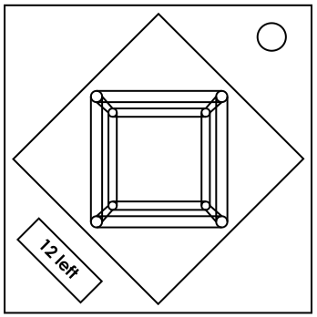
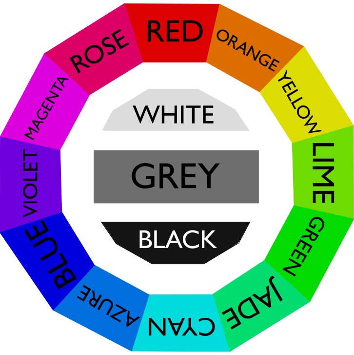
This module consists of 12 wires arranged in the shape of a cube, each attached to metal vertices. Each wire is uniquely colored according to non-grayscale colors in Appendix COLOR, and the cube rotates 11 times. There is also a screen in the bottom-left corner; if you are highlighting a wire, the screen will show the wire’s color. Otherwise, the screen will show the number of uncut wires.

To solve the module, cut all 12 wires using the rotations and relations between the wires. Cutting a wire out of order will incur a strike, but will not change the rest of the solution.

There are 14 distinct rotations that can appear on the module, specifically 6 rotations involving 2 axes and 8 rotations involving 3 axes. However, the module will generate 8 2-axis rotations and 3 3-axis rotations. The order in which rotations are positioned is random.

Defining Axes

As this module works in 3D space, there are 3 possible axes: X, Y, and Z. When looking at the module straight on:

  • The positive X-axis goes east.
  • The positive Y-axis goes away from the back of the module, becoming closer to the viewer.
  • The positive Z-axis goes north.

The opposite applies for negative axes. The module diagram in the top-right of this page depicts all 3 axes and their directions.

2-Axis Rotations

In a 2-axis rotation, exactly one positive axis will transform into a different positive axis, while the third axis stays in place. A 2-axis rotation is notated as the initial positive axis followed by the resulting positive axis. An “XZ” rotation, for example, has the positive X axis transforming into the positive Z axis.
3-Axis Rotations

In a 3-axis rotation, all 3 axes transform into new distinct axes. 3-axis rotations have a more complicated process:

  • Look at some positive axis and call it W. Note down the axis that it rotates into and call that axis V. V can be either positive or negative.
  • Repeat this, but with the way positive V (and specifically positive V) rotates into the remaining axis U. Prepend the direction U is rotated into.
  • Repeat this again with U going into W.

In an example rotation “-X+Y-Z”, what is originally the positive X-axis rotates into -Z, +Z rotates into +Y, and +Y rotates into -X. All rotations are realistically represented in 3-dimensional space, so there will always be an even number of negative axes.

RotationPriority
XY ROYLGJCABVMS
XZ BCMGYROVJSAL
YX MLGRAYJSBCOV
YZ GBLVYMOSRCAJ
ZX ABCGJLMORSVY
ZY CGVBRLSYAJMO
+X+Y+Z RYGCBMOLJAVS
+X+Z+Y OCLBGYMVRAJS
-X+Y-Z YSJBGVCAMLOR
-X+Z-Y GORYSBLAVCJM
+X-Y-Z CRAOBYVLMGSJ
-X-Z+Y MSVAJOGLYCBR
+X-Z-Y BRSVAMLGOJYC
-X-Y+Z VOCABLRYMSGJ

Rotations are cyclic, meaning that you can start the notation from anywhere; “-X+Y-Z” can also be written as “+Y-Z-X” or “-Z-X+Y”. However, this manual will start rotations with the X-axis for simplicity.

Cutting Wires

For each of the 11 rotations, find them in the table on the right to gain a priority string of letters. Each letter represents the first letter of a wire color, except that R is Red while S is Rose. Use the priority string and the instructions on the next page to determine which wire to cut for each rotation.

If the rotation involves two axes, take the Nth and (N+1)th colors in the corresponding priority string (N is the current rotation of the sequence, starting with 1). If the two wires with those colors share a vertex, cut the first color in the rotation’s priority string whose wire is not already cut. Otherwise, cut the second such color in the priority string.

If the rotation involves three axes, take the corresponding priority string and remove all wire colors that have been cut. Go through each adjacent pair of colors in the priority string (not wrapping around) until you encounter a pair of colors where the wires are on the same axis, and cut the second wire in the pair. If none of the pairs have colors that are on the same axis, simply cut the first uncut color in the priority string.

By this point, if you did everything correctly, there should be one uncut wire remaining. Simply cut the last wire to solve the module.

Appendix COLOR: Button Colors

Grayscale colors (White/Gray/Black) will never appear on the module.

Highlighting a wire will always cause the bottom-left display to show the wire’s color, regardless of whether or not colorblind mode is enabled.