N-d coordinate system version 1.0
The N-d coordinate system is designed to work for a variable number of dimensions, ranging from 3 to 9, hence the N, which is a natural number.
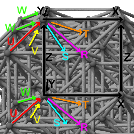
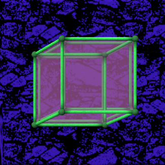
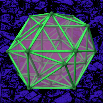
To the right you see a figure showing a 9 dimensional representation of this coordinate system, mapped to a 9 dimensional cube. In this special case, every axis points along an edge of the cube.
Every rotation is described by the two axes which enclose the plate that is rotating. If the 9-cube, as shown in the image, were to rotate clockwise then this would be a rotation of the plane enclosed by X and Z.
If looking at the bottom left vertex, then it would move along the Z axis and then along the X axis, making this an ZX rotation. If looking at the top right vertex, it would be a -Z-X rotation, which is the same as ZX, as shown below.
Converting negative rotations to the default notation:
The default notation is made of two axis letters, written uppercase, without any minus signs, e.g. XZ or ZX, but not X-Z, -XZ, nor -Z-X.
| Input |
Default Notation |
| +X+Z |
XZ |
| -X+Z |
ZX |
| +X-Z |
ZX |
| -X-Z |
XZ |
The table to the right shows how to convert rotations to the proper notation, which is then used by modules.
The basic way of doing it is by swapping the two letters if the number of minus signs is equal to 1, and then removing all minus signs.
Additional Notes:
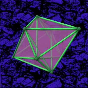
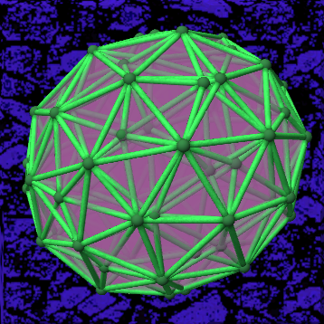
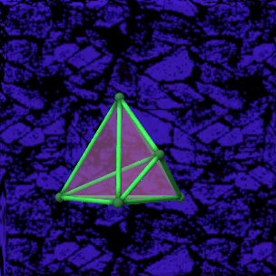
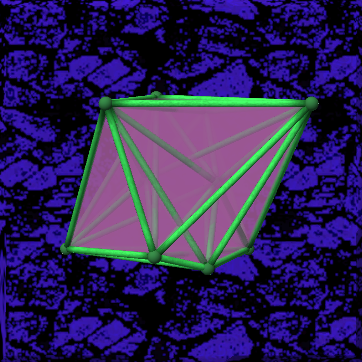
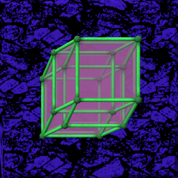
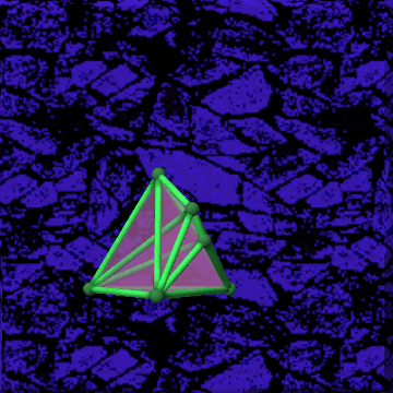
The axis-edge alignment only works for shapes which are made up solely of square faces. For other shapes this coordinate system can also be used, but is more difficult to read, as following an edge is not possible.
For shapes of less than 9 dimensions, some axes will be omitted, starting at R, followed by S T U V W. Similarly, for higher shapes extra axes would be added.