On the Subject of Signals
Do you know what a camelback looks like?
There is an oscilloscope screen on the Signals module. It shows a signal from either Channel A or Channel B. The channel to display can be chosen using channel selector CS.
- Channel A (CS in left position) is connected to a given input signal.
- Channel B (CS in right position) is connected to the signal generator.
To disarm the module, setup the generator to generate the correct signal for the given input signal (see Table 1) and press button B to submit.
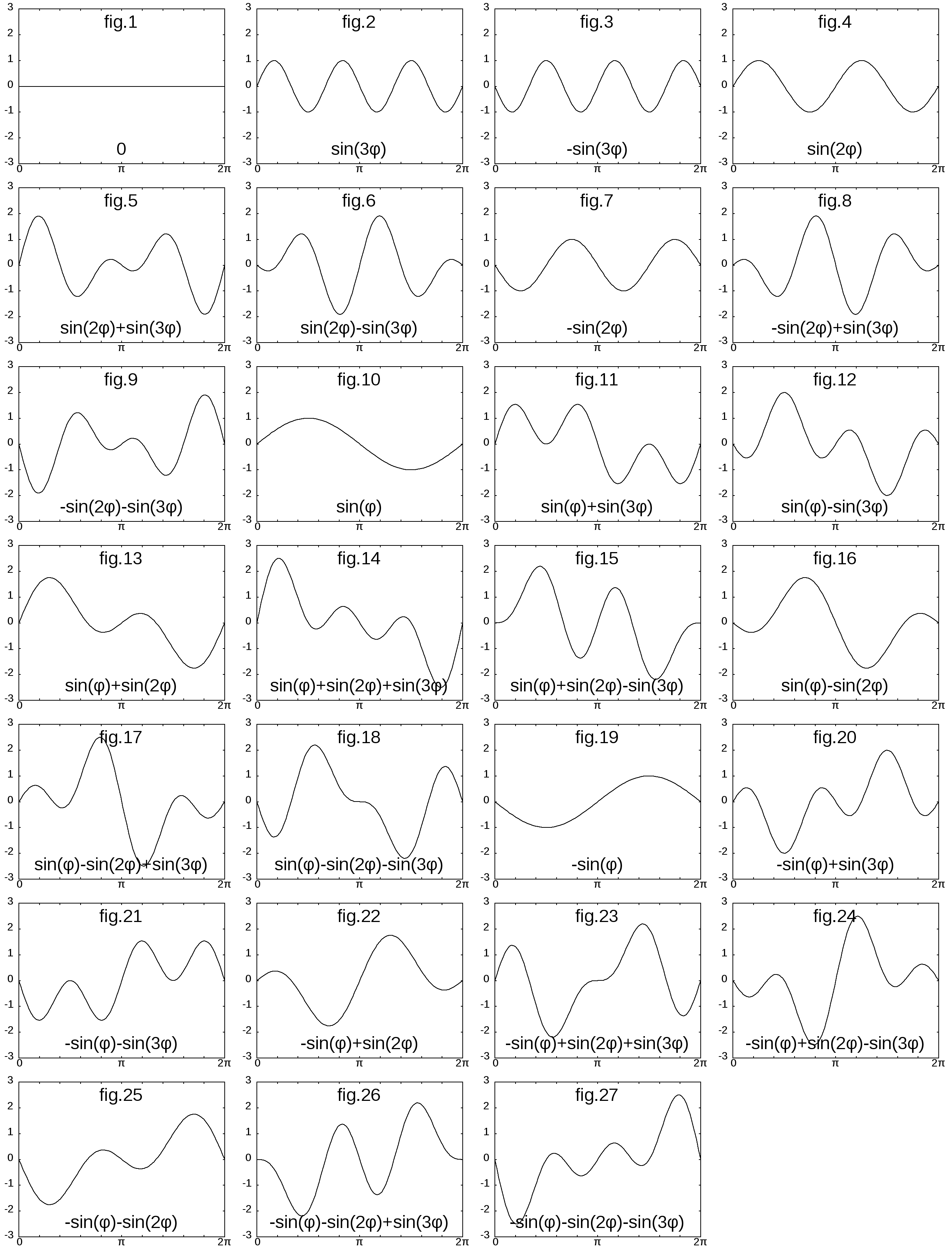
Refer to pictures fig.1 ... fig.27 to identify the input signal and use Table 1 to find the required generator signal.
The Signal Generator:
The generator product is an additive synthesis of three harmonic components:
g(φ) = C1.sin(φ) + C2.sin(2φ) + C3.sin(3φ)
Coefficients C1, C2 and C3 are controlled using switches S1, S2 and S3.
All the switches have three available positions, which are translated to the following coefficient values:
- 0 (the component is not present in the output signal)
- 1 (the component is added with a positive coefficient)
- −1 (the component is added with a negative coefficient)
!!! Caution - wiring of switches S1, S2 and S3 is randomly shuffled !!!
Each coefficient is exclusively controlled by one of the switches S1, S2 or S3, but it is not known which switch should be used to control coefficient C1, C2 and C3 and how the switch position translates to the coefficient value.
- Tip 1: To decipher switch wirings, find the generator switch arrangement that produces a constant signal (fig.1) first. From this point, the switch wirings can be deciphered easily.
- Tip 2: The input signal can be identified by re-creating an identical signal using the generator and then identifying the signal by looking at switch arrangement and referencing deciphered switch wirings.
- Pro-tip: Seeing the generator signal for only three wisely-chosen switch arrangements gives you all the information that’s needed to fully decipher wirings for all the switches.