
On the Subject of Switch Placement
What if you’re only one flip away? Better try another guess.
-
Using the colors and orientations of the switches in the 5×5 grid, determine the
correct states for all twelve switches. The module will automatically solve when
all the switches are in their correct states.
-
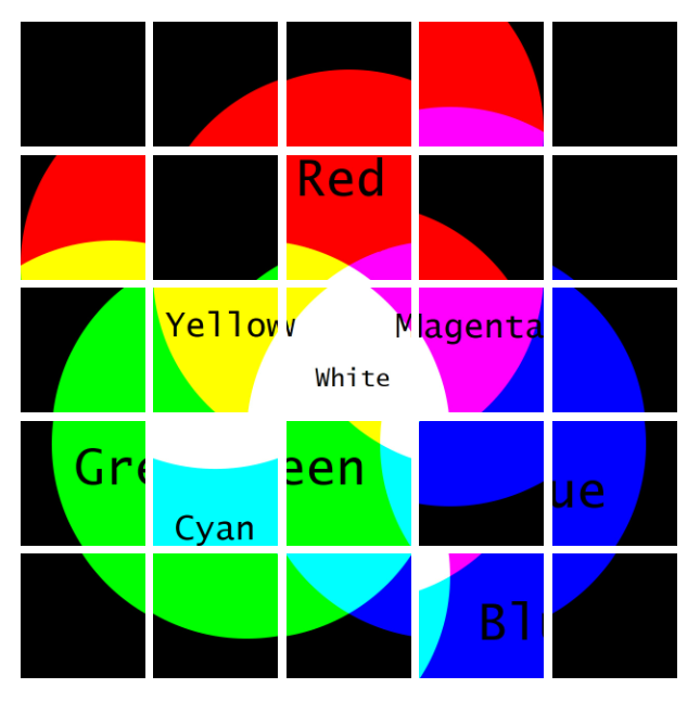
Each switch occupies two “paired” cells in the grid. The coloring for the switches
uses RGB mixing (see Appendix rGb).
| R > G, B |
G > R, B |
B > R, G |
Two-Way Tie |
Three-Way Tie |
|
Appendix
rGb |
 |
H - V <= -4 |
| H - V = -2 |
| H - V = 0 |
| H - V = 2 |
| H - V >= 4 |
Find the key column and row using the information provided on the module. R, G, and B
refer to the number of switches which contain the red, green, and blue channels respectively.
H and V refer to the number of horizontal and vertical switches.
All horizontal switches which occupy a cell in the key column must be flipped towards the key
column. Likewise, all vertical switches which occupy a cell in the key row must be flipped
towards the key row.
To find the correct states for the remaining switches, find the table whose D equals the
direction from the center cell that its paired cell is. Starting from the intersection of the
key column and row, and processing the cells from there in numerical order (wrapping around to
1 if necessary), flip the switch at the current cell towards the current cell if its correct
state has not been identified yet.
| D = ⇧ |
|---|
| 23 | 8 | 21 | 16 | 25 |
| 20 | 15 | 24 | 7 | 12 |
| 9 | 22 | 13 | 4 | 17 |
| 14 | 19 | 2 | 11 | 6 |
| 1 | 10 | 5 | 18 | 3 |
| D = ⇦ |
|---|
| 6 | 17 | 13 | 4 | 25 |
| 1 | 22 | 8 | 14 | 20 |
| 21 | 12 | 3 | 19 | 10 |
| 16 | 2 | 23 | 9 | 15 |
| 11 | 7 | 18 | 24 | 5 |
| D = ⇨ |
|---|
| 11 | 1 | 6 | 16 | 21 |
| 17 | 7 | 22 | 2 | 12 |
| 23 | 13 | 18 | 8 | 3 |
| 9 | 24 | 4 | 14 | 19 |
| 5 | 20 | 15 | 25 | 10 |
| D = ⇩ |
|---|
| 1 | 2 | 5 | 6 | 7 |
| 24 | 3 | 4 | 9 | 8 |
| 23 | 22 | 25 | 10 | 11 |
| 20 | 21 | 16 | 15 | 12 |
| 19 | 18 | 17 | 14 | 13 |